Tower Defence

A visually stunning tower defence game, awarded full marks. Also known as Photon Defence...
Please note, this is a first revision and there are bound to be mistakes.
Game Play Video:
Features Video:
Introduction
In the second half of my final year at Sheffield University I took a module called Computer Games Technology. The module evaluation was entirely based on an assignment, and the assignment was to create a game – a remake of the classic tower defence game. It was required that we work in a group to implement the game and optimize it using nVidia’s GPU computing technology – CUDA. The basic requirements of the game were to contain a path (a route for the enemies from a start point to an end point), contain many of one type of agent (enemy), contain one type of tower, be playable in 2D and have demonstrable CUDA optimization of the agents.
Higher marks were obtainable by implementing some of the following; multiple paths or difficulty levels, different (upgradable) towers, timed waves of agents, different types of enemies (with varying attributes), an editor mode, a multi-player mode, controllable towers, a 3D view, path blocking, and variable agent strength. We achieved many of these and were (the only group to be) awarded full marks for our implementation (and report).
Concept
The goal of tower defence games is to try to stop enemies from crossing a map by building towers which shoot at them as they pass. Enemies and towers usually have varied abilities, costs, and ability costs. When an enemy is defeated, the player earns money or points, which are used to buy or upgrade towers, or upgrade the number of money or points that are earned, or even upgrade the rate at which they upgrade.
Tower defence games are characterised by the positioning of static units by the player to defend against mobile enemy units who are trying to get from a start point to an end point. There is a set number of enemy units (or 'damage' the player can take from units reaching the end point) who can reach the end point before the level is lost. Some games use a static route that the enemy units follow around which the player places their towers, while others favour a free-form environment that allows the user to define the path the enemy units take. Some games use a mixture of both. Most games allow the upgrading of the player's towers.
Quoted directly from Wikipedia
Game Features
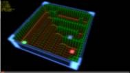
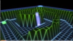
It was decided that our implementation of the tower defence concept would be very different from most available. One of the biggest differences is that it does not have the option to block paths, or for that matter start with an empty terrain and create your own defensive maze. The terrain layout is defined by the current level, which ensures that high land where turrets can be placed must be used strategically to ensure no lives are lost.

Agents start from a fixed start point and make their way to a fixed end point that is clearly marked on the terrain. The player starts with a certain amount of credits for each level which they can use to buy or upgrade turrets. For each agent killed they get more credits and for each to reach the end they lose a life. If they lose all the lives (also defined by the level) they lose the level and have to start again.
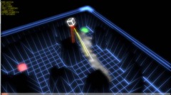
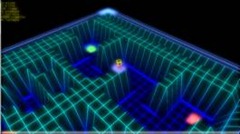
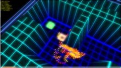
To create a more novel user experience we made it a rhythm game and incorporated a 3D camera as well as the classic top-down 2D camera to allow the user to explore the terrain and take in the dazzling graphical effects. With a keyboard and mouse the 3D camera is easy to control but it is more difficult with console controllers so we also created a hybrid control method (discussed later).
First Prototypes
One of my team mates – James, and I had previously created a few OpenGL prototypes, experimenting with different technologies, one of which was a shader based terrain system. For the main game we started with this prototype which was primarily written by James. I started implementing a basic camera system while James started on a new prototype for the agents.
It was not long before we had agents ‘swimming’ around on an earth-like terrain, constrained by a simple bounding algorithm.
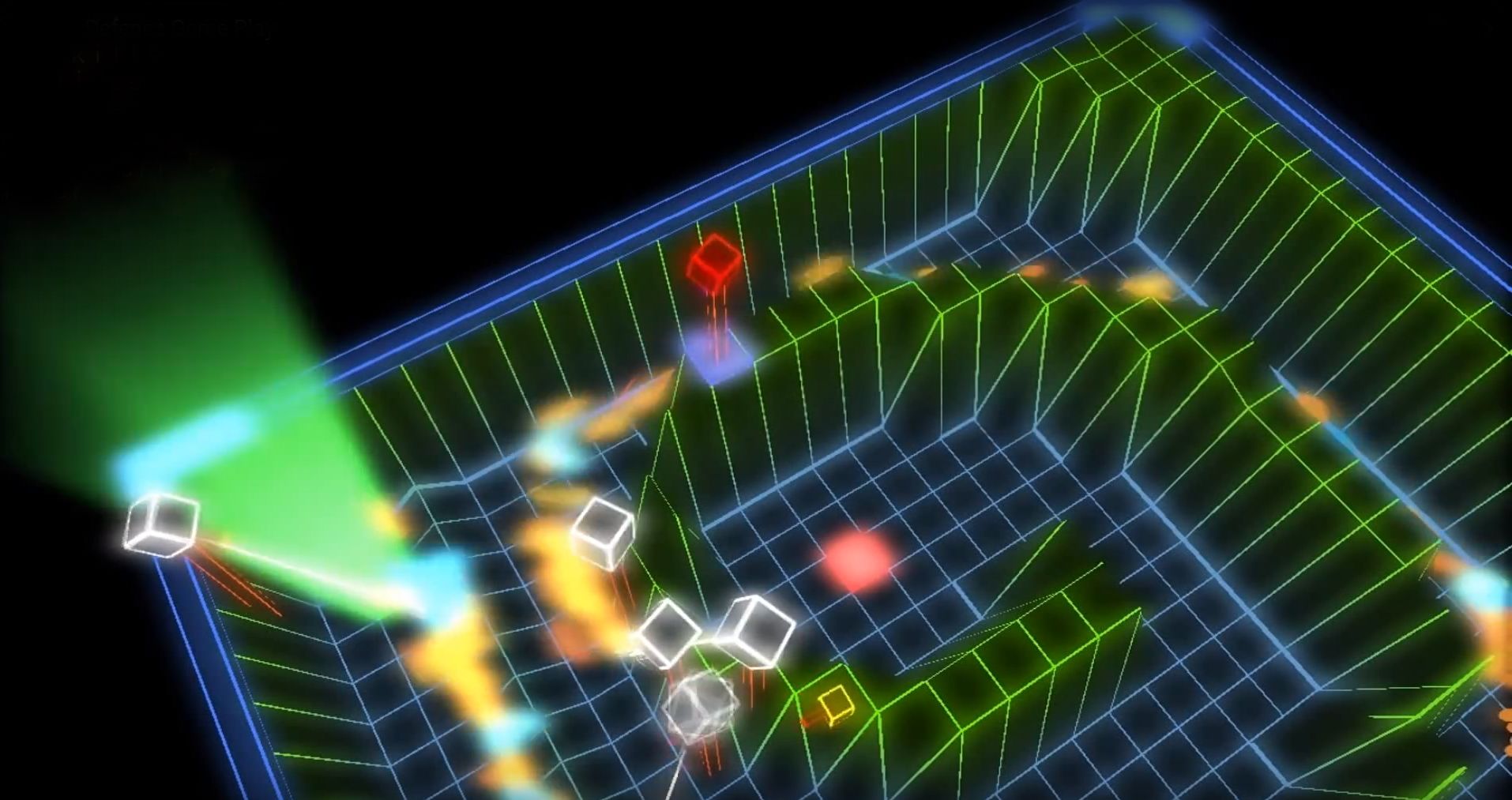
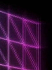
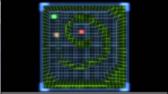
It looked pretty bad, the scene just looked awkward and out of place, we decided it needed a more novel look - the earth-like terrain did not fit. We have always liked Geometry Wars for both the game play and the graphics and thought it would look amazing if we had a Tower Defense game that was visually akin to Geometry Wars. While James worked on the agent movement I began implementing a glow post-processing system. The initial results while successful were a little crude, and lacking a few refinements which are detailed later on.
Glow
Applying glow to a scene is a post-processing procedure which means it is done after most, if not all of the other rendering is complete, depending on what the effect should be applied to. The glow effect is applied to the rasterised image of the scene and not the raw scene elements itself, so the first step is to render the entire scene in a way that can be further processed.
Render to panel
This is done by rendering the scene to a texture using a Frame Buffer Object (FBO). Once the scene is rendered to a texture it can then be rendered to a quad through a shader or shaders allowing effects to be applied to the scene.
Blur
The glow effect is essentially an accumulative blur effect. The glow or blur process ideally requires the source image to be processed at least two times, once to add the effect horizontally and once to add the effect vertically. More 'passes' can be applied to increase the effect but each additional pass incurs two more processing steps which can dramatically slow down the time required to render one frame and therefore reduce the frame rate.


Each time the shader processes the rasterized image it is also given a direction (horizontal or vertical) in which to blur. The fragment shader (as always) processes each pixel and in the blur shader each pixel is set based on the surrounding pixels. The shader examines a predefined number of pixels either side of the desired pixel in the direction passed to the shader, the colours of pixels are accumulated with a weighting based on the distance between the pixel being processed and the pixel being examined. Pixels with a lesser distance have a greater weight. The colour is not accumulated on top of the colour already at that location (the colour from the scene texture) though, as stated later, the original image is rendered after all the glow passes, over the top. If it is accumulated then horizontal and vertical flaring occurs.
Multi Pass
To build up the intensity of the glow realistically, building on both the vertical and horizontal components the scene was sent through the glow proccess twice, this required four passes - two horizontal and two vertical. Fortunately the glow process is not detail sensititve and using a lower resolution rasterised image to create the glow often (and in this case did) produce a better effect. We opted to half the original resolution in both dimensions (a quarter of the size) which meant that the 4-pass glow process addressed the same number of pixels as running the full size scene once through a fragment Shader.
Therefore the final glow process involved:
● Rendering the original scene at full size to FBO0
● Rendering the texture from FBO0 on a quad at a quarter of the size through the horizontal blur shader to FBO2
● Rendering the texture from FBO2 on a quad through the vertical blur shader to FBO1
● Rendering the texture from FBO1 on a quad through the horizontal blur shader to FBO2
● Rendering the texture from FBO2 on a quad through the vertical blur shader to FBO1
● Rendering the texture from FBO1 on a quad, scaled up to full size and overlaying the original scene texture from FBO0 over that (using multitexturing in the shader)
This gave us a nice glow effect that was relatively fast and did not have a major impact on our frame.

Problems
Initially our terrain’s grid was rendered using glLines but they have a fixed rendered width when rasterized, for example if the camera is moved far from the terrain the grid lines are exactly the same width in pixels as if you are as close as possible. Unfortunately when the terrain is further away the grid lines are closer together, but because with glLine they are the same width they appeared to become disproportionately bigger and ‘brighter’ which did not look good. We changed the terrain system to draw proportional grid lines, which is discussed in the next section.
The Result
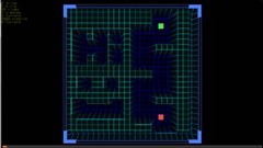


Terrain
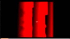
Height Mapping
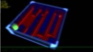
The terrain is a grid made up of triangles, the more efficient triangle strips could not be used because it produced adverse effects in the picking system (discussed later on). The resolution of the grid (the size of the triangles) is fixed for all terrains and affects many factors. The height of each vertex is used to generate a blocking map which determines where the agents cannot go and where turrets can be placed, based on whether the terrain height is above a certain threshold. Changing the resolution of the terrain then changes where the height approximations sit which can effect how the level behaves.
The height values are taken from an image, only one channel is considered so for all intents and purposes the image is grey-scale. Higher colour values represent higher points in the terrain. The height values are applied directly to the z dimension of the terrain vertices. In terms of OpenGL space, the terrain is rendered in the range of (0, 0) to (1, 1) and then scaled up to the desired size so that regardless of the resolution and the size the bounds of the terrain are always easily known within the shaders without passing any extra parameters around. The terrain is then stored in a display list so that in each frame it can be called up quickly and does not need to be regenerated.
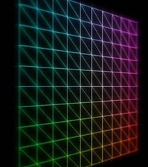
Grid
Highlights are applied at regular intervals to give the appearance of a grid. The separation intervals of the grid are the same size as the resolution of the grid, so the appearance of the lines coincide with height changes in the terrain. As previously noted, glLine was initially used for convenience but the appearance was not desirable
The colour of the terrain (determined and discussed later on) is modified based on the x and y texture coordinates of the current pixel. Colour values could be used but they are required for the grid cell picking (cell selection, discussed in later a section). The x and y coordinates are multiplied up to a suitable range as by default they range between 0 and 1, for example multiplied by 100. The modulus of the new coordinates is taken with a factor of the multiplier (for example x mod 10), if the result is 0 then the colour is brightened, otherwise it is dulled giving the appearance of the grid. A multiplier of 100 and modulus parameter of 10 will give 11 grid lines and therefore 10 grid spaces. Setting the multiplier and parameter higher (for example 1000 and 100 respectively) would create thinner grid lines.
By producing the grid lines in the fragment shader and not using glLine the grid lines now become proportionally larger and smaller dependant on the camera’s distance from them. With the original glLine method the grid lines had to sit just above the terrain itself so they were always visible, but if the camera was close enough the gap between the terrain and the lines could still be scene. Applying them in the shader also gets round this issue as the terrain colour itself is manipulated.
We wanted the terrains to blend smoothly between levels but because display lists are used to store them the display list would require regenerating for every frame during the transition. To avoid this the height values for the next level are stored using the z component of the texture coordinate of the current level. When the level is complete an interpolation value, starting from 0 and increasing to 1, is passed to the shader over the desired number of frames and the heights are interpolated in the vertex shader between the vertex z and the texture z based on the aforementioned value. The colour values are also interpolated but they are passed as shader variables as there are only two per level (therefore four per terrain, two for the current level and two for the next). After the transition is complete the display list for the next level is used. The display lists for all levels are generated when all the levels (and therefore terrains) are loaded when the program starts therefore there is no perceivable delay in the transition process.

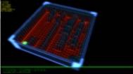
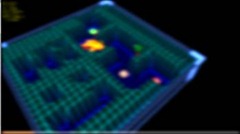
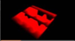
Terrain Colouring
The terrain is coloured very simply, based on height. The fragment shader takes two colours, a low and high one. The colour for any pixel of the terrain is a mix between the low and high colours based on the height at that pixel. A pixel with no height will be purely made up of the low colour and a pixel with maximum height will only be the high colour. The two colours for the next level are also passed to the shader and the mix for each pixel is interpolated as per the interpolation value during the transition process.
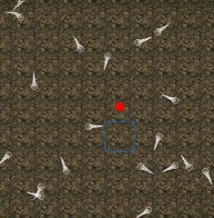
Picking
So that a player can place a turret on a specific grid cell the terrain coordinate indicated by the cursor must be determined. With a fixed 2D view it would be easy to calculate the coordinates, but with a movable 3D view there is a greater challenge as there is the potential for the camera to be at any angle and position making projection calculations more difficult. Furthermore even if the projection calculations are done correctly, at certain angles a higher part of the terrain may be in front of projected target which could cause the wrong cell to be selected. We implemented a colour based picking system to ensure accurate selection of terrain cells.
The first element to be rendered is a plain version of the terrain with only special cell colours and height but no other elements and no shaders are used. Each cell is assigned a unique colour, not visually unique like red vs. green but just actually unique (254,0,0) vs. (255,0,0). A reference map is maintained mapping each colour to the corresponding cell. The colour at the cursor’s current position is read and translated back to a cell position using the reference map. The scene is then cleared and the actual game scene is drawn. The user never sees the picking terrain scene.
As previously mentioned, triangle strips cannot be used to render the terrain due to the picking system because if the vertices of each side of the quad (made up of triangles) are given one colour and the vertices of the other side are given a different colour they will blend in the middle of the triangles and the cell will not have only one colour.
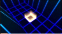
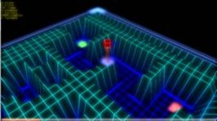
Cell markers
A means of indicating specific cells was required so that the start and end points were obviously defined, and so that the currently selected cell for turret placement was clear. All the markers were coloured cubes which fade using the alpha channel in the fragment Shader based on the texture coordinate of the pixel in question. The texture coordinates were set so that the cube faded out as z increased. The start and end markers were fully coloured cubes whereas the cursor marker used a method similar to the grid rendering to highlight the edges of the cube giving the appearance of a more precision selection.
The top side of the start and end markers were also scaled on x and y as the agents spawned and finished respectively in proporton with the number of agents spawning or finishing the time. The base of all markers was adjusted so that they always appeared to sit on the surface of the terrain.

Shader manager
In the entire game there are several shaders, many of which are used more than once in several different places. While it is often considered more efficient to render objects by shader where possible to avoid shader switching the time constraints of the project did not allow for this. So that shaders are only loaded once and not duplicated we wrote a shader manager to cache shaders. At any point in the code a shader can be requested using an identifier and if it has not previously been loaded it will be compiled and the reference to it will be stored along with the identifier so any use at a later time can switch to the shader by switching using the reference.
Turrets
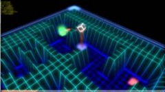
In this tower defence game the towers are referred to as turrets, and they fire lasers. A player with enough money can build and upgrade the turrets on the high sections of the terrain.
Head Movement and Target Locking
When idle then turret heads rotate at a fixed speed, waiting for a target to come in to range. Once a target is selected the turret head moves to target it and only begins firing once the turret is pointing directly at the target. The idle speed and targeting speed are different with the targeting speed being faster. Upgraded turrets (discussed later) also have different speeds.
Originally the turrets targeted and shot at the closest target, but when many targets fly past the tower is often continuously changes target and then spends more time targeting rather than shooting because it does not shoot until it is aimed at the target. The targeting system was changed to bring it more inline with the behaviour of many games. Instead of just targeting the closest target, the turrets pick the closest target and locks on to it until it either dies or goes out of range, at which point it picks the next closest target in range.
CUDA Targeting
CUDA is used to calculate the closest agent to a target at any given time. The process has been specifically designed to work well on a highly parallel architecture. First a CUDA kernel generates a list of alive agents for each turret, then for each turret a kernel is used to compare pairs of agents, each time selecting the closed of the two, then comparing again with the result of another kernel until only the closest agent for each turret remains.
Turret Aim and Laser Positioning
The turrets aim then fire at the targeted agent, the angles of the turret head are calculated using simple trigonometry. The laser angle is calculated in a similar way, translating the center to the midpoint between the turret head and the agent (necessary for the laser decay discussed later). Unfortunately these trigonometry calculations require a square root which is a notoriously expensive calculation and often avoided if at all possible.
Targeting the closest agent within range also requires a trigonometric calculation to work out the distance between the turret head and the agent. However the exact distance need not be known as the closest agent needs locating that falls within a range, but if the range is specified as a squared number then the potential square root in the targeting calculation is obsolete.
Laser Decay
To give a more visually impressive effect the 'lasers beams' fired from the turrets were not recycled as soon as the next shot was fired. Instead after each shot the 'beam' was added to a decay list. Every beam in the decay list appeared to fade away with each frame until they were no longer visible and were removed from the list. Originally the alpha blending was used to fade out the lasers but because of issues in OpenGL with alpha and depth testing the lasers often appeared either in front of or behind other objects when they shouldnt. To combat this we stopped using alpha blending and instead scaled the 'beams' towards the center, with the glow post processing this gave a very similar effect to alpha blending without the depth testing issues.
Upgrades
When a player gains more credits by destroying agents they can either buy more turrets or upgrade the existing ones. A reference map is maintained of all the current turret locations with a pointer to the particular instance at that location. When the turrets are upgraded the instance is instructed to upgrade and it internally updates the parameters to improve the turrets range, strength, movement rate and targeting rate.

Agents
Rendering
Initially agents were rendered in their entirety as four connected circles but with a future plan to move the agents to a Vertex Buffer Object (VBO) so their position can be easily manipulated by CUDA and the graphics card we changed how they were passed to the graphics card. They are passed as points which means each agent is simply made up of four points and therefore 4 vertices rather than the 40+ it would require to make them from circles. A geometry shader was then used convert the points into circles meaning the bandwidth between the host and the graphics card was reduced dramatically and they could be easily stored on a much smaller VBO which would be easily modifiable from CUDA. Experiments were done comparing parametric generation of circles to static generation (a list of points rendered where desired) and surprisingly the parametric generation was faster. Our time constraints did not allow for investigating the reason for such a result.

Soft body physics
The body sections of the agents are connected by virtual springs, which make up part of a soft body physics system used in the game. It allows them to stretch slights and for the tails flick about as the agents change direction.
Swarms and Types
To ensure the game remains interesting there are different types of agents. The lowest level of agents move quickly but do not have much health. The next level up of agent is slower, with more health but when it dies several low level agents are released from it’s remains. The is one level of agent above that which is slower still and has even more health, but when it dies it releases several agents of the next level down which will each in turn release several low level agents upon their demise. The type of agent initially spawned is based on the level’s rhythm track (discussed later) which determines how many agents spawn, and when they spawn. If at any given time there are a minimum number of agents, a higher-level agent will be spawned instead, and there is a high threshold for spawning the highest-level agent too.
Time based animation
As a primary goal of the project was to use and demonstrate CUDA’s ability to improve the performance of parallel computation in graphics we decided to develop with v-sync turned off so that we could observe the raw frame rate. As v-sync gives a processing time buffer by limiting the frame rate, frames that take slightly longer but less than the maximum frame time at a given frame rate are not visible. With v-sync off the frame rate can fluctuate rapidly, and of course v-sync is just a limit, on a slow computer the frame rate can vary under that limit too.
If crude animation adjustments were made, like adding one every frame to a rotation value then the speed to the animations would change proportionally with the frame rate and would clearly not be smooth and regular. We implemented time based movement and animation on all object and the camera, so the rate at which the scene and camera moved did not vary, regardless of the frame rate.
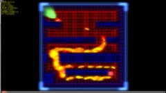
Path finding
The A* path finding algorithm is used to instruct the agents on how to navigate from the start to the end. For each level the A* map is generated in advance due to the computationally expensive nature of the generation process and passed to the CUDA kernel so it is available in every frame for the agent movement calculations. The agents can also be influenced by each other and the heights of the terrain. They loosely flock together but avoid the terrain walls so that they always remain in the valleys. They are also capable of going down multiple paths and each have random variations in movement and turning speed to ensure they do not all take the same ‘perfect’ path. The game does not support blocking the agents because the A* map is generated in advance.
Control and Input
The game currently supports four different types of input, the conventional keyboard and mouse, an Xbox 360 controller, a Nintendo Wiimote and an easy to use hybrid constructed from both an Xbox 360 controller and a Nintendo Wiimote.
Xbox
The Xbox controller is very easy to interface with, the XInput library provides a simple interface that can acquire all the controller inputs and control the vibration in a handful of lines of code. It can also rapidly detect the addition or removal of other Xbox controllers. The Xbox controller made it easy to navigate the 3D view but more difficult to control the location of the cursor to place turrets in both views as few people appear to find it intuitive to use a controller stick to manipulate a cursor.
Wii
After concluding that the Xbox controller did not provide the easy input method expected we decided to try using the Wiimote as we thought the natural pointing might make it easier to position the cursor whereas the nunchuck and D-Pad would make it easy to navigate around (as with an Xbox controller).
After testing several libraries we settled on WiiYourself, a native C++ library that supported all the Wiimote functions we required. The Wiimote can detect up to four infrared dots two of which are usually provided by the ‘sensor bar’ (it is not a sensor, just two infra red LEDs). The left and right dots must be tracked, and the difference in angle between them can be used to work out the rotation of the WiiMote, whereas their delta of their position between frames can be used to detect their movement in two dimensions. To detect full 360 degree rotation the left and right dots must be tracked even if the wiimote is rotated upside down, as rotation was not important to us this was ignored.
Of the four infra red point trackers the wiimote has, it does not consistently use the same ones to return the position of the dots. The dots from all of the trackers were considered, two are usually discarded as they will not contain a dot. The remaining two were then examined and based on their position one was considered to be the left dot and the other the right. Then the delta of the average of the two was used to move the cursor. This average combined with a bit of smoothing provided stable, smooth cursor control.
Unfortunately the Wiimote also has the D-Pad and the nun chuck has the joystick which is generally counterintuitive for FPS style controls as most would look around with the dominant hand and navigate with the other, but it is also common to point the Wiimote with the dominant hand. Having the Wiimote pointer and the D-Pad in the dominant hand made navigation somewhat confusing and awkward, though it was better than the Xbox controller.
Hybrid Controller
The hybrid controller was made by attaching the WiiMote and the Xbox controller together. The 3D camera movement is controlled using the XBox controller in conventional FPS style and the cursor is controlled by aiming the controller (essentially the WiiMote) at the screen. After a short while getting used to it, many players found it quite intuitive.
Level Generation
In each level agents spawn in time with an associated music track. The timing is not based on any form of audio analysis, instead a rhythm is recorded using an electric drum kit with the drummer playing in time with the song. The hits on each drum pad or cymbal are recorded, and the magnitude of the hit and type of pad determine how many agents are spawned.
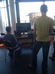
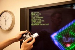
Exposure
Before the required demonstration date this game gained enough recognition for it to be demonstrated at an AI conference at York and a day for school children at Sheffield University.