Creating a completely isolated guest network using Mikrotik hardware
Creating a physically isolated guest network using iptables and 802.11q VLANs.

Introduction
By way of a preface, my home network is not simple - this is not your average "home" network.
This is another project finished a while ago, in early 2020 that I've had the time to write up.
Recently I switched my (crappy) Netgear "managed" switches for an array of second-hand MikroTik "routers" from eBay (at a similar cost to the new Netgear kit since the MikroTik kit quite niche, which makes the resale value attractive).
They are powerful, complex, cost effective and from what I can tell a bit of a marmite product - some love them and some hate them. I like them, at least until things stop working.
All of the above is a digression from the title and the purpose of the article.
Some of my client work requires me to work with their devices on a local network, and since the broader uptake of working from home, that means these devices exist on my home network. I generally would not want client devices interacting with my home network, and vice versa, and especially if a client device created a public wireless network.
A conventional 'guest network' is often created at the wireless AP level and employs client isolation to ensure wireless clients cannot talk to each other. This is fine until the devices to be connected are wired.
This post looks at creating a separate subnet within the main network that cannot see the wider parent network but can access the internet to be able to do it's job - in this sense it is complete in so far as it works at the network level, rather than using a concept like client isolation. Clients on the guest network can see each other in this case, but not the core network and without very intimate knowledge and adding some custom routes the same is true of the core network to the guest network.
The solution present here is complex and not ideal in the way it works so it is likely to evolve over time.
My Network

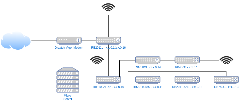
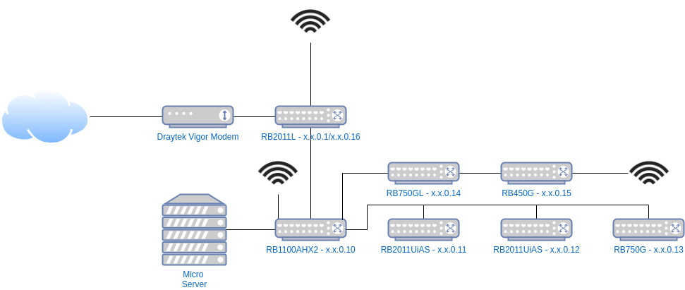
The diagram above shows my current network setup, each layer being a floor, and I am fortunate to have an internal (to the walls) CAT6A wired network throughout the house connecting all the key switches.
On top of the 8 switches, server, Fire TVs, TVs, Xboxes, smart devices and other bits, I have more than 50 daily devices that connect directly or wirelessly. As a result I run a /23 subnet to allow for a decent address space for blocks of DHCP reservations, various other transient devices (lots of Pis, ESPs, etc) and the odd visitor.
The internet comes in via the Phone-line (ADSL2) to the Draytek modem in bridge mode and is connected to via the RB2011L at the top which establishes the PPPoE connection, as well as providing NAT services to the local network.
The RB1100AHx2 is the 'Core Switch' linking most of the others.
The Micro Server runs DNS and DHCP through dnsmasq.
Otherwise, it's quite simple, while all the routers are used as switches and are smart, they're not configured to do much.
That is, until, the guest network was created.
The Guest Network
The guest network is consumed via the switch at x.x.0.12 which is on my desk.
The guest network lives on VLAN10 whereas the default is VLAN1.
Unless otherwise configured, all the switches default each port to VLAN1 untagged, which means any traffic on those ports is assumed to be on VLAN1 and traffic spanning from those ports, on dumb switches or wireless APs is the same.
There are two ports on my desk switch which are set to be on VLAN10 untagged - meaning any traffic on those ports is assumed to be and attributed to VLAN10.
At this point the virtual LAN network is isolated, but largely useless as there is nothing providing a bridge between VLAN10 and VLAN1, where the wider connectivity is available.
Untagged VLANS are associated by the switch.
The 802.11q protocol allows for packets to be sent on a given tagged aka explicitly declared VLAN. For this to work the switch has to allow that VLAN on that port too, so you can't just snoop on any VLAN at will. In addition, to the best of my knowledge, you need smart/managed switches anywhere that multiple VLANs will be transported (or trunked) over a single link.
Here's how the gap is bridged:
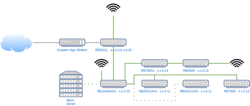
- The Micro Server is on a port where
VLAN1is untagged andVLAN10is available tagged. - The uplink between the Core Switch (where the Micro Server lives) and my desk trunks
VLAN1andVLAN10. - My desk switch has the uplink to the Core Switch trunking
VLAN1andVLAN10too, as well as defaulting most ports toVLAN1untagged and the guest ports toVLAN10untagged. - The NAS runs
dnsmasqon the mainVLAN1(physical) interface and the virtualVLAN10interface dnsmasqprovides DHCP and DNS on bothVLAN1isx.x.0.x/23VLAN10isx.x.254.x/24- The Micro Server provides forwarding (NAT) from
VLAN1toVLAN10, and the RB2011L (at the top of the diagram) providers upstream forwarding to the internet fromVLAN1 - The Micro Server blocks upstream traffic from the
VLAN10subnet toVLAN1using IP tables, except when forwarded via the gateway - The setup is effectively double NAT'd:
Internet <=> RB2011L@x.x.0.0/23 (NAT) <=> Micro Server (NAT) <=> Guest@x.x.254.0/24

In the diagram above the dotted green lines represent VLAN1 and VLAN10 coexisting, all other links are normal untagged VLAN1.
On the core switch setup we can see the VLANs:

Ports 10 and 13 are the Micro Server and uplink respectively that are both untagged and tagged (Port 2 is for a RaspberryPi to connect to client devices via a WiFi dongle for development and testing - outside the scope of this post).
On my desk:

Ports 9 and 10 are untagged to 10, the rest are untagged to 1 (10 is disconnected right now).
From this point the traffic is well isolated but the Micro Server needs setting up to route traffic.
Networking and Routing
VLAN Interface
The netplan configuration is updated to add a VLAN interface on the existing interface with the address x.x.254.50.
network:
 version: 2
 renderer: networkd
 ethernets:
   enp2s0:
     dhcp4: no
     dhcp6: no
     addresses: [x.x.1.50/23]
     gateway4: x.x.0.1
     nameservers:
       addresses: [8.8.8.8,8.8.4.4]
 vlans:
   vlan.10:
     id: 10
     link: enp2s0
addresses: [x.x.254.50/24]Packet Routing
Enabling masquerade in iptables allows the machine to perform the classic NAT we experience on a home network but in this case between from x.x.254.x/24 up to x.x.0.x/23 (and then up to the Internet).
Running the following command will add the rule:
iptables -t nat -A POSTROUTING -o enp2s0 -j MASQUERADE
This is what the nat table will look like if this is the only rule in place.
Chain PREROUTING (policy ACCEPT)
target     prot opt source               destination

Chain INPUT (policy ACCEPT)
target     prot opt source               destination

Chain OUTPUT (policy ACCEPT)
target     prot opt source               destination

Chain POSTROUTING (policy ACCEPT)
target     prot opt source               destination
MASQUERADE all -- anywhere anywhere We need to enable forwarding on the VLAN interface, but without allowing packets to be forwarded to the parent / home network. The first command drops (blocks) those undesirable packets, and the second allows any remaining packets to be forwarded.
iptables -I FORWARD -d x.x.0.0/23 -j DROP -i vlan.10@enp2s0
iptables -A FORWARD -i vlan.10@enp2s0 -j ACCEPT
The filter table will be as follows if these are the only rules:
Chain INPUT (policy ACCEPT)
target     prot opt source               destination

Chain FORWARD (policy ACCEPT)
target     prot opt source               destination
DROP       all  --  anywhere             x.x.0.0/23
ACCEPT     all  --  anywhere             anywhere

Chain OUTPUT (policy ACCEPT)
target prot opt source destination Finally, enable IP forwarding on the Kernel by finding and updating the line below (the line will be net.ipv4.ip_forward=0 by default or commented out, if you don't find it then add it):
net.ipv4.ip_forward=1Using iptables-save and iptables-restore from the package netscript-ipfilter makes it easier to manage rule sets, the full saved rules are as follows:
# Generated by iptables-save v1.8.4 on Fri Jan  1 15:57:59 2021
*filter
:INPUT ACCEPT [478:77890]
:FORWARD ACCEPT [106:18159]
:OUTPUT ACCEPT [154:13406]
-A FORWARD -d x.x.0.0/23 -i vlan.10@enp2s0 -j DROP
-A FORWARD -i vlan.10@enp2s0 -j ACCEPT
COMMIT
# Completed on Fri Jan  1 15:57:59 2021
# Generated by iptables-save v1.8.4 on Fri Jan  1 15:57:59 2021
*nat
:PREROUTING ACCEPT [349:104685]
:INPUT ACCEPT [334:103521]
:OUTPUT ACCEPT [34:2803]
:POSTROUTING ACCEPT [8:531]
-A POSTROUTING -o enp2s0 -j MASQUERADE
COMMIT
# Completed on Fri Jan  1 15:57:59 2021
To save, run: iptables-save > /etc/iptables/rules.v4
To restore, run: iptables-restore < /etc/iptables/rules.v4
As usual a greater level of detail can be found elsewhere on how to implement the restore part of the life cycle on boot, along with other solutions.
Guest devices can ping 8.8.8.8 (as an example of Internet access) and x.x.254.50 (the NAT router/Micro Server) but not anything on x.x.0.0/23 including x.x.0.1 which is the upstream router.
Dnsmasq
dnsmasq is used to perform both DNS and DHCP service. I moved away from bind9 and dhcpd-server to achieve better cohesion between DHCP leases and their corresponding local DNS entries, which it has certainly improved.
The Easy Option
A quick and easy option is to serve up all leases from a single dnsmasq instance. Between the localise-queries option, and the multiple dhcp-range entries the server will provide the right range to the queries coming into and served from their respective interfaces.
The tagging feature is used to segregate DNS options and reservations, lan is applied to all leases served up on the range and interface and guest is applied to those on the VLAN and accompanying range.
Option 3 is the gateway - which is the main router for the home range and the Micro Server for the guest range.
Option 6 is the DNS servers to be used.
interface=enp2s0
localise-queries
domain-needed
bogus-priv
filterwin2k
no-resolv
local=/home.net/
server=8.8.8.8
server=8.8.4.4
listen-address=127.0.0.1
listen-address=x.x.1.50
expand-hosts
domain=home.net

dhcp-lease-max=100
log-dhcp
dhcp-sequential-ip
dhcp-authoritative

# HOME RANGE
dhcp-range=set:lan,x.x.1.100,x.x.1.200,120h
dhcp-option=lan,3,x.x.0.1
dhcp-option=lan,6,x.x.1.50,8.8.8.8,8.8.4.4

# x.x.0.10-20 - Network Equipment (New)
dhcp-host=xx:xx:xx:xx:xx:xx,SOME_NAME,x.x.0.10

# GUEST RANGE
listen-address=x.x.254.50

dhcp-range=set:guest,x.x.254.100,x.x.254.200,12h
dhcp-option=guest,3,x.x.254.50
dhcp-option=guest,6,x.x.254.50,8.8.8.8,8.8.4.4

dhcp-host=guest,xx:xx:xx:xx:f8:92,wifi-client,x.x.254.51,24h
Clearly there is a lot going on in the configuration above - the manpages for dnsmasq are comprehensive so its best to look at that to understand each directive.
Configuration changes can be checked by running dnsmasq --test before restarting the service.
As a bonus, its easy to view and monitor leases in /var/lib/misc/dnsmasq.leases, e.g. watch -n 1 -d cat /var/lib/misc/dnsmasq.leases.
The main downside to this approach is that many configuration options are global, between both interfaces, and in part, as a side effect, all the hostnames and DNS entries are associated with the same domain, and the dnsmasq instance will serve results on either interface - while the likelihood is arguably slim, devices on their respective subnets could discover the addresses of those on other subnets. Only the addresses could be exposed but it still, in theory, increases the potential attack surface.
The Fully Isolated Option
Most dnsmasq options are global or can be called more than once, but without tagging there is no concept of scoping (compared to nginx/apache configs, for example, which are hierarchical).
There is a little misinformation floating around that suggests if you using the conf-dir option to include files in a folder it can serve completely different configurations on different interfaces. This is incorrect as the various config files are effectively interpreted as a single file and in the case of options that cannot be repeated, the last is taken (e.g domain), but nothing is scoped or acts like it is scoped, except the options that support tagging - implied and limited scoping (1 level deep).
Using multiple files is likely better used for breaking up range configurations and lease reservations.
The prevailing opinion is that it is better to run a dnsmasq instance per interface in cases where there are materially different options, such as the domain name to name one global directive.
The default systemd setup for running dnsmasq is quite involved as it is entangled between a number of files including:
/etc/init.d/dnsmasq/etc/default/dnsmasq/lib/systemd/system/dnsmasq.service
While the system service setup is complex and arguably comprehensive, he actual command that runs as a result will look similar to this:
/usr/sbin/dnsmasq -x /run/dnsmasq/dnsmasq.pid -u dnsmasq -7 /etc/dnsmasq.d,.dpkg-dist,.dpkg-old,.dpkg-new --local-service --trust-anchor=[snip]-x provides the pidfile location, -u is the user to run as, -7 is the config folder, --local-service tells it to only accept queries on the local subnet(s) and --trust-anchor relates to DNSSEC.
To keep it simple, the systemd dnsmasq service is disabled as two new dnsmasq services are run using supervisor.
The config lives in /srv/dnsmasq/home.conf and /srv/dnsmasq/guest.conf respectively, again to keep it separate. I've opted for single file configs here but in future may break out lease reservation groups into other files.
To stop and disable the systemd dnsmasq process run:
systemctl stop dnsmasq.service
systemctl disable dnsmasq.service
It would be possible to have one run in systemd and the other under supervisor.
Supervisor Config
After installing supervisor (via apt install supervisor) create two config files:
[program:dnsmasq-home]
command=/usr/sbin/dnsmasq --no-daemon -u dnsmasq --conf-file=/srv/dnsmasq/home.conf --trust-anchor=[snip]
autostart=true
autorestart=unexpected
startsecs=10
startretries=3
stopwaitsecs=10[program:dnsmasq-guest]
command=/usr/sbin/dnsmasq --no-daemon -u dnsmasq --conf-file=/srv/dnsmasq/guest.conf --local-service --trust-anchor=[snip]
autostart=true
autorestart=unexpected
startsecs=10
startretries=3
stopwaitsecs=10These two files declare the home and guest dnsmasq processes. The main differences to the systemd version is that the --conf-file is specified, to avoid defaulting to the /etc path, and we swap -x ... for --no-daemon which runs it in the foreground (which supervisor prefers). The --trust-anchor argument was copied from the systemd command (captured using ps waux | grep dnmasq).
The two dnsmasq config files are similar to before, with a few key changes:
interface=enp2s0
listen-address=127.0.0.1,x.x.1.50
bind-interfaces

domain-needed
bogus-priv
filterwin2k
no-resolv
no-hosts
local=/home.net/
server=8.8.8.8
server=8.8.4.4
expand-hosts
domain=home.net

dhcp-lease-max=100
dhcp-leasefile=/var/lib/misc/home.leases
log-dhcp
dhcp-sequential-ip
dhcp-authoritative

dhcp-range=x.x.1.100,x.x.1.200,120h
dhcp-option=3,x.x.0.1
dhcp-option=6,x.x.1.50,8.8.8.8,8.8.4.4

# x.x.0.10-20 - Network Equipment (New)
dhcp-host=xx:xx:xx:xx:7d:61,SOME_NAME,x.x.0.10
interface=vlan.10
except-interface=lo
listen-address=x.x.254.50
bind-interfaces

domain-needed
bogus-priv
filterwin2k
no-resolv
local=/guest.net/
server=8.8.8.8
server=8.8.4.4
expand-hosts
domain=guest.net
log-dhcp
dhcp-authoritative

dhcp-lease-max=100
dhcp-leasefile=/var/lib/misc/guest.leases

dhcp-range=x.x.254.100,x.x.254.200,12h
dhcp-option=3,x.x.254.50
dhcp-option=6,x.x.254.50,8.8.8.8,8.8.4.4

dhcp-host=xx:xx:xx:x:f8:92,wifi-client,x.x.254.51,24h
The key differences are as follows:
- In both we bind to interfaces and IPs - the bind interfaces makes the process more selective about binding
- Guest does not bind to
lowhich is a default, to avoid a clash - Each can and does have its own domains
- Each has its own lease file
- No need to localise queries
- Tags are not used
Conclusion
The net result is exactly as desired using two dnsmasq processes, however it took a while to sift through the various Stack Overflow posts to conclude the best approach. It also took a while to get the right configuration options to ensure DHCP bound to the interface declared when using the 2 process setup.
The main downside for me is that this is a very complex setup and easy to break - removing the DROP rule from iptables removes the only line of defence between the two subnets.
On the plus side, you can connect anything to the slave ports on the switch, APs or dedicated devices and they act in isolation to your main network.
Of course there are other options, such as having both networks as sibling NATs under a higher NAT - but The Internet seems less keen on lots of NATs, and I can empathise with that.
Another potential issue is that any traffic and activity from the guest network is still linked to your network and public IP address.
I plan to try out a few other ideas in future posts, including moving the setup largely as is to the MikroTik routers, and exploring the concept of a plug-and-play private and isolated network.
Hints and Tips
Renewing a DHCP lease
On Ubuntu the DHCP lease can be renewed with sudo dhclient -r; sudo dhclient -v which first releases the lease then re-runs the DHCP client, in verbose mode so the results are easily viewed.
Killed old client process
Internet Systems Consortium DHCP Client 4.4.1
Copyright 2004-2018 Internet Systems Consortium.
All rights reserved.
For info, please visit https://www.isc.org/software/dhcp/

Listening on LPF/eno2:avahi/74:78:27:28:07:1f
Sending on   LPF/eno2:avahi/74:78:27:28:07:1f
Listening on LPF/br-ea82fb8c1ea1/02:42:35:65:fd:9e
Sending on   LPF/br-ea82fb8c1ea1/02:42:35:65:fd:9e
Listening on LPF/br-acc267f58b24/02:42:12:6e:87:d6
Sending on   LPF/br-acc267f58b24/02:42:12:6e:87:d6
Listening on LPF/br-ab86c4435ca5/02:42:25:13:b0:6e
Sending on   LPF/br-ab86c4435ca5/02:42:25:13:b0:6e
Listening on LPF/docker0/02:42:ac:45:c0:5d
Sending on   LPF/docker0/02:42:ac:45:c0:5d
Listening on LPF/wlo1/68:54:5a:7f:92:25
Sending on   LPF/wlo1/68:54:5a:7f:92:25
Listening on LPF/eno2/74:78:27:28:07:1f
Sending on   LPF/eno2/74:78:27:28:07:1f
Sending on   Socket/fallback
DHCPDISCOVER on eno2:avahi to 255.255.255.255 port 67 interval 3 (xid=0xb5a8d85f)
DHCPDISCOVER on br-ea82fb8c1ea1 to 255.255.255.255 port 67 interval 3 (xid=0xcc217408)
DHCPDISCOVER on br-acc267f58b24 to 255.255.255.255 port 67 interval 3 (xid=0x6e74ec24)
DHCPDISCOVER on br-ab86c4435ca5 to 255.255.255.255 port 67 interval 3 (xid=0xbab1076c)
DHCPDISCOVER on docker0 to 255.255.255.255 port 67 interval 3 (xid=0x48c29866)
DHCPDISCOVER on wlo1 to 255.255.255.255 port 67 interval 3 (xid=0x57295b7a)
DHCPDISCOVER on eno2 to 255.255.255.255 port 67 interval 3 (xid=0x2b13ab00)
DHCPOFFER of x.x.1.24 from x.x.1.50
DHCPREQUEST for x.x.1.24 on wlo1 to 255.255.255.255 port 67 (xid=0x7a5b2957)
DHCPACK of x.x.1.24 from x.x.1.50 (xid=0x57295b7a)
cmp: EOF on /tmp/tmp.dAiYzuyfjt which is empty
bound to x.x.1.24 -- renewal in 180836 seconds.
DNS Settings
On the latest Ubuntu the DNS settings can be viewed with resolvectl status.
Monitoring listener bindings
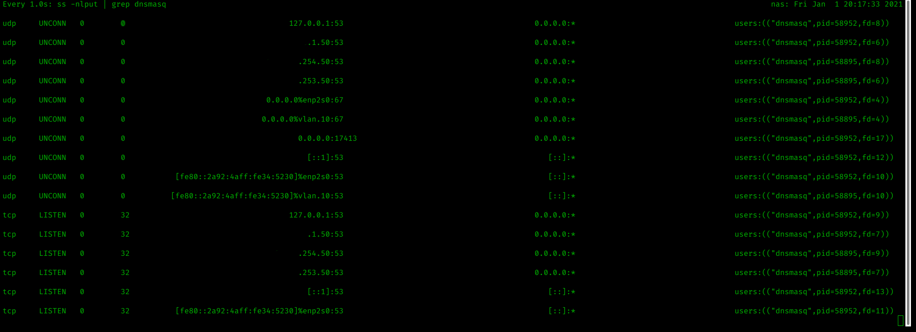
While trying to ascertain why the configuration for dnsmasq and the 2 process setup was fighting for DHCP port UDP/67 I was using lsof -i -P -n to view listening connections, the problem is that it isn't possible to see which interface the connection is listening on.
The following result, while bound to 0.0.0.0 can be scoped to just one interface.
dnsmasq 58895 root 4u IPv4 277252 0t0 UDP *:67I found the following solution on Stack Exchange:
ss -nlput | grep dnsmasq
Will show the TCP/UDP sockets for the process dnsmasq.
-n
no port to name resolution-l
only listening sockets-p
show processes listening-u
show udp sockets-t
show tcp sockets
An example output is below:

