RGB LED Electric Drums - MIDI x Arduino x WS2812

Introduction
This is another just-for-fun project which was completed a couple of years ago. I have a number of instruments that I play for the pleasure of it, having had an electronic drum kit for a few years and having had and acquired all sorts of electrical, I was interested in combining an RGB LED strip with the drum kit to produce a sound and light show.
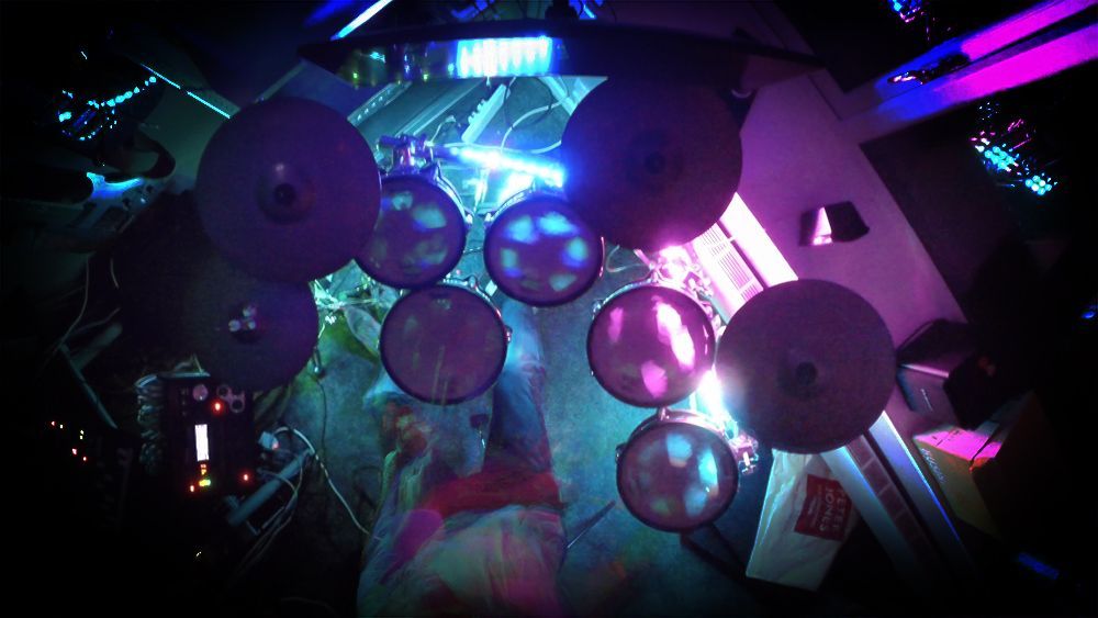
Before going into lots of detail, the video below demonstrates via a quick drum solo the relationship between the sound and lights:
There are more demo videos at the end of the article.
The project was started and finished about 3 years ago but it took a little time to put together a nice demo video to accompany the write-up.
Not long before I attempted this project, when the WS2812 series LEDs started becoming quite popular and somewhat affordable (still too much compared to today) I bought a 5 metre strip.
This was at a similar time to a sharp rise in the popularity of Arduino over the less accessible and often more expensive platforms like the PIC microcontrollers. The Arduino support for the WS2812 LEDs was and is very good, so inevitably I moved away from PIC entirely.
I figured it would be good fun to have light effects matching the music being played on the drums.
I am fortunate to have a Roland TD30-KV Drum kit, but this project should work with any device (drums or otherwise) with MIDI output.
Note: Due to the low-light conditions required to film this it is all quite noisy, grainy and low-quality.
All together to replicate this you will need:
- 2 x Arduino (any should do - I had an Uno and a Mega spare, I'll explain why 2 are needed shortly)
- (Optional) MIDI Shield for one of the Arduinos
- A WS2812 strip or lights
- A 5V Power Supply (suitably powerful enough for the LED strip)
- A MIDI instrument
The High Level Concept
The goal is to have the Arduino read the midi data using one pin, each note received over midi would trigger an 'animation' on the LED strip which would be controlled via another pin. The logic would be as follows:
while True
  read midi
  update animations
  update LEDs
end
More work (and code) is required to map the MIDI notes to some sort of LED sequence and then handle that sequence to completion. That will be covered further down in the Software section.
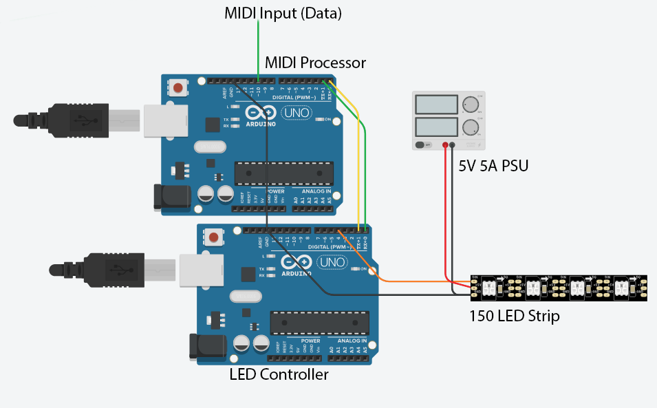
Two Arduinos?
The first attempt, using a Raspberry Pi, wasn't quite right, the processing delay and low processing power of the older Pis combined with an interpreted language created a noticeable visual lag. Attempt two was more successful, using Arduinos, running only the code required for this project in response to direct inputs.
In my early testing using on Arduino I observed strange issues where some of the MIDI notes would get lost.
Many communication protocols are timing sensitive, including both the MIDI and WS2812.
As I understand it, the NeoPixel library most commonly used to drive the WS2812s, makes the precise 800Khz timing happen by using a couple of little tricks, have a look at the show method for more info. My best guess is that the delays or possibly exclusively consumed execution cycles cause the MIDI library to miss data as there is no hardware buffer when using a Software Serial port.
To get around this issue I used two Arduinos talking to each other over a Serial port. One Arduino listens to the MIDI messages, maps those triggers onto animations and sends the resulting 'render' to the second Arduino which updates the LED strip based on the serial data.
In the midi-reading code there are a number of places where the MIDI messages are checked as even small delays appear to cause issues. Ideally a simple loop as conceptualised above would do the job, however the reality is more like:
Arduino 1
while True
  for each animation
    update animation
    read midi
  end
  for each led
    write led to serial
    read midi
  end
  while less than 5 ms have elapsed
    read midi
  end
end
Arduino 2
while True
  read serial
  update leds
end
In essence the MIDI messages are checked between nearly every small operation that if done all at once would incur too large a delay. There may be timing delays on the inter-arduino communications but the serial buffer should help with this, and we can also afford to miss 'frames' if needed - which is described later on.
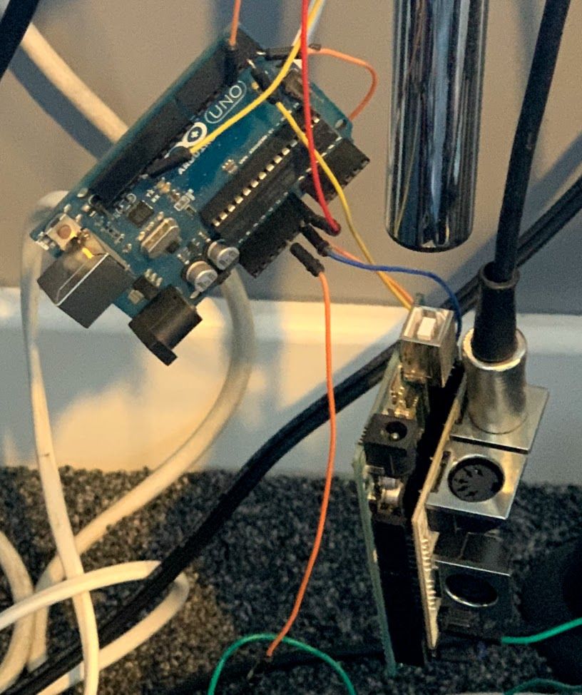
Hardware Setup
The hardware itself is relatively simple. The two Arduinos need to be able to talk to each other over serial, this will need disconnecting for programming when using a single Serial port.
The LED Strip will almost certainly need external power as they are very power hungry. That same power source can power the Arduinos too if they are running without USB power.
The MIDI Shield
I am currently using a MIDI Shield but I do not believe this is strictly required to 'listen' to the MIDI signal. It does provide good optical isolation, so that any power fluctuations do not cross between devices and potentially harm them, and it allows for other things like MIDI Output and Passthrough.
On the Uno I believe I am effectively using a software Serial port but a hardware port may allow for better buffering and less MIDI timing issues. One option may be to use software Serial to send the LED signal to the other Arduino as the Serial buffer is likely to be of less use there as worst case missing the odd LED Frame is less noticeable than missing a note.
Software
As discussed above, there are two high level components interpreting the MIDI notes to produce a visual display and controlling the actual LED Strip.
I have described the LED Control first as it is the recipient of the core logic and hence knowing how that works makes it easier to understand the MIDI Processor.
LED Control (Arduino 2)
This is the rgb_serial folder in GitHub.
The first Arduino handling MIDI is doing the Lion's share of the work, the second Arduino (described here) is simply visualising the serial data feed.
After initialising the Serial port a simple test is executed sequencing the colours through the LED strip and then resetting to off. This is a primitive visual indicator that the lights are connected and working, if this works but nothing else it would suggest a communication issue between the Arduinos.
In the main loop the Serial port is monitored and if any data is available the first byte is read. There is a simple command structure in that the first byte my have a value of 255 to indicate the start of a message. The second byte is then the command, 253 causes the strip to reset to all off, sending a 253 back over the Serial channel. A command of 254 tells the device we are going to 'render' a new display to the LED strip. After the command byte the next byte represents the render length (ie. the number of LEDs). Following this each sequence of 3 bytes represent R, G and B values respectively, for every 3 bytes we receive the 'pixel' at the current offset is set. Once we have set all the values communicated by the length value the LED strip is updated with the NeoPixel show() method and a 254 byte is sent back.
Currently a helper function allows the execution to wait for at least 3 bytes to read. This appears to cause the strip to 'hang' on occasion possible due to an out of sequence communication from a the Serial buffer filling. In theory it has a timeout but no mechanism to break since read() is blocking. At some point I will fix this by checking available() and breaking if it is < 3, indicating a timeout, or perhaps returning a bool as to whether the timeout was hit.
The control bytes at the start make it possible to drop frames and resume on the next one.
In theory the R, G and B values could be clamped at 252 (and optionally scaled) to ensure there is no overlap and avoid the need for escaping. This is not currently the case in the code - but could be easily implemented.
MIDI Processing, Animation and Decay (Arduino #1)
This is the midi_rbg folder in GitHub.
Definitions
Before we get into meaningful code there are a number of definitions to consider.
A few simple ones, an IDLE_TIME is defined, at the start, and if there are no other triggers after the IDLE_TIME a simple animation plays to confirm communication and verify the decay logic.
The number of LEDS are also defined, in my case there are 149 - the first one died after a PSU mishap...
After that some of the most important definitions - the drum note byte mappings, for me they are as follows:
#define HIHAT_TOP 46
#define HIHAT_TOP_CLOSED 42
#define HIHAT_RIM 26
#define HIHAT_RIM_CLOSED 22
#define HIHAT_PEDAL 44
#define CRASH_TOP 49
#define CRASH_RIM 55
#define RIDE_TOP 51
#define RIDE_RIM 59
#define RIDE_BELL 53
#define SPLASH_TOP 57
#define SPLASH_RIM 52
#define BASS 36
#define SNARE 38
#define SNARE_RIM 37
#define SNARE_RIM2 40
#define TOM1 48
#define TOM1_RIM 50
#define TOM2 45
#define TOM2_RIM 47
#define TOM3 43
#define TOM3_RIM 58
#define TOM4 41
#define TOM4_RIM 39
Electronic Drums are complex, you have main and rim triggers as well as others for some cymbals like the hi-hat and ride. I worked these out using a an Arduino Mega, printing the note values to the Computer's Serial link - this code is not committed anywhere unfortunately. A USB-Midi device and software can achieve the same.
After the notes we have some duration values, for animation (more on this later):
#define SHORT 200
#define MEDIUM 300
#define LONG 400
Setup()
During the setup process, after initialising the Serial port and MIDI library a 'reset' is requested which issues the reset command described above and waits for the confirmation - this should get the devices in sync, following that a different test light sequences is sent over the Serial channel to confirm that the link is working followed by a final reset.
Now we add the Triggers. These map a Note to a set of LED's to turn on, a colour and a duration (from the constants above).
A Trigger is represented with a C++ class which handles the data values and the decay. Adding a Trigger in setup() adds an instance of the Trigger class to the triggers vector with the list of triggers of LED sequences to be triggered with the R, G, B values and the duration. A helper function produces a range of LEDs to trigger by specifying the start, end and step - essentially providing an in-line for-loop that produces discreet values.
Multiple Triggers can be added for a note allowing for different LEDs, colours and delays to be invoked for a single event. Some of the triggers invoke LEDs local to the instrument whereas others like the bass, snare and hi-hat trigger sequences along the whole strip, reflecting their impact on the overall song and drum score. There are 50 triggers in this project.
Idle Sequence
The Idle (after 20 seconds) is as follows:
void idleSequence(const unsigned long now) {
  if ((now - lastIdleAt) > 300) {
    lastIdleAt = now;
    if (idleCount == 0) {
      handleNote(BASS, 1.0f);
    } else if (idleCount == 1) {
      handleNote(SNARE, 1.0f);
    } else if (idleCount == 2) {
      handleNote(TOM1, 1.0f);
    } else if (idleCount == 3) {
      handleNote(TOM2, 1.0f);
    }
    ++idleCount;
    if (idleCount >= 6) {
      idleCount = 0;
    }
  }
}
It sequences through a few 'triggers' to show the link is working.
MIDI
The arduino_midi_library is used to read the MIDI messages which can be installed using Arduino's Library Manager.
As noted previously, timing is exceptionally important with the MIDI process. The responsibility is delegated to a function entitled handleMidi which first checks if a message is available. If there is one (or more) the type is checked - we only care about NoteOn events since drums do not have user-controlled sustain (mostly).
In handleMidi() when a note is received the 'force' is calculated and passed along with the byte value note identifier to handleNote. Here we invoke another class named ActiveTrigger - as the name suggests it is a trigger that has been activated, and more importantly it handles the render which in this case is the fade-out decay
void loop()
The main loop focuses on the animation decay, taking the vector of ActiveTrigger entities, traversing them and decaying as per the spec, removing any that have fully decayed.
As described above, of course, in every loop we check for any MIDI activity.
Once the 'loop' is complete we write the 'rasterized' result to the Serial channel.
Finally, we sleep for a newborn-challenging 5 milliseconds - yes, that's right - unlike the average new-parent night we expect to get to get a good sleep once in 200 cycles... (Seriously, if you know how to achieve this let me know - I'm still waiting 700+ cycles in!).
void handleNote()
When a note hits home work is required. We take the note and gather all related triggers, along with the force and add it to the std::vector of activeTriggers.
Re-entering the void loop()
And hence we return - every time this loop is triggered, which is literally every time the Arduino executes, we have work to do. iterating through the activeTriggers we decay the values and add/subtract them to the global r/g/b accumulators that drive final result sent over the Serial channel, with a little clamping for fun...
Once they fully decay they are of-course removed.
This certainly makes for some visually pretty shit!
Every loop cycle we write out the r/g/b buffers to the Serial port, sending them to the Arduino controlling the LEDs using the clearly indestructible protocol.
Of course, in all code there is some helper magic making the world hang together - but in any case this is a good primer.
Check out the full code base to see how it all works.
The Code
All the code is available on GitHub. It probably needs a bit of a tidy-up.
As noted above, there are two key folders:
The rgb_serial folder is the code to control the LEDS.
The midi_rbg folder takes the MIDI signals and sends the raster over serial to the other Arduino.
The Hardware