Creating Virtual Static IP with Mikrotik, CHR and AWS

My ISP does not provide me a dedicated public IP address either dynamic or static by default*.
Instead I have a private address behind a shared public IP.
While Internet access works fine, I cannot set up custom port forwarding and as a result cannot access devices on my network directly from the Internet.
In this post I have outlined one of many potential solutions, using Mikrotik routers and a CHR instance, to enable port forwarding to via a static public IP.
* My ISP does sell static IPs as an add-on.
ISPs and NAT
The majority of, if not all, home and office networks will use Network Address Translation to allow multiple devices at that location to access the Internet.
ISPs will usually provide homes with one public IPv4 address, and the same will be the default for businesses though they can often purchase more IPs or blocks of IPs if they have sufficient justification.
According to Wikipedia:
Network address translation (NAT) is a method of mapping an IP address space into another by modifying network address information in the IP header of packets while they are in transit across a traffic routing device.[1] The technique was originally used to bypass the need to assign a new address to every host when a network was moved, or when the upstream Internet service provider was replaced, but could not route the network's address space. It has become a popular and essential tool in conserving global address space in the face of IPv4 address exhaustion. One Internet-routable IP address of a NAT gateway can be used for an entire private network.[2]
As network address translation modifies the IP address information in packets, NAT implementations may vary in their specific behavior in various addressing cases and their effect on network traffic. The specifics of NAT behavior are not commonly documented by vendors of equipment containing NAT implementations.[2]
It's also worth noting the IPv6 stance on NAT (again, from Wikipedia):
Network address translation is not commonly used in IPv6 because one of the design goals of IPv6 is to restore end-to-end network connectivity.[26] The large addressing space of IPv6 obviates the need to conserve addresses and every device can be given a unique globally routable address. Use of unique local addresses in combination with network prefix translation can achieve results similar to NAT.
ISP NAT Diagram
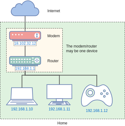
In the diagram above the private network has a subnet of 192.168.1.0/24 and the router has an IP of 192.168.1.1. The client devices on the network have distinct IPs on the same range. The modem (which may be built into the router) also has a public IP. The router translates the local requests in both directions as they depart and return to the router, whereas the modem provides transit to the wider network, in this case the Internet.
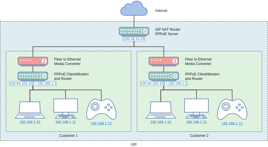
Carrier Grade NAT
My ISP runs Carrier Grade NAT (a.k.a CG-NAT or CGN).
As defined by wikipedia:
Carrier-grade NAT (CGN or CGNAT), also known as large-scale NAT (LSN), is an approach to IPv4 network design in which end sites, in particular residential networks, are configured with private network addresses that are translated to public IPv4 addresses by middlebox network address translator devices embedded in the network operator's network, permitting the sharing of small pools of public addresses among many end sites. This shifts the NAT function and configuration thereof from the customer premises to the Internet service provider network.
Carrier-grade NAT has been proposed as an approach for mitigating IPv4 address exhaustion.
It's often seen with mobile carriers and smaller ISPs.
Restrictions
The CG-NAT setup means that my network, running NAT behind my ISP, is behind (at least one) other NAT layer run by the ISP.
Access to The Internet works fine, but I cannot setup things like IP Forwarding, and services or applications reliant on direct peer-to-peer connectivity (e.g with UPnP) are likely not work, though I don't expect this to be a significant issue as most services do not rely on peer-to-peer connections they just use the opportunistically.
Note: The 100.64.0.0/10 IP address is a shared address space for use in ISP Carrier Grade NAT.
Motivation
I run a number of utility services from my Home network, including applications to manage the smart lighting, monitor the CCTV, notify us of visitors and so on.
Most of these have web interfaces that it is useful to access while on the go.
This means access is usually from a mobile device and it is ideal not to have to connect to VPN, for example to quickly check the CCTV when the doorbell rings.
What resolves to is that it is ideal to be able to access services at home, directly and securely, via a public IP, which would conventionally be realised using the port forwarding settings on the router, and potentially dynamic DNS if the public IP is not static.
The Approach
I have previously written about how my home network consists largely of MikroTik routers/switches and this has informed part of my approach.
The RouterOS software each router runs can perform a wide array functions and services, largely regardless of the underlying hardware, including running VPN tunnels and customising NAT/Firewall rules.
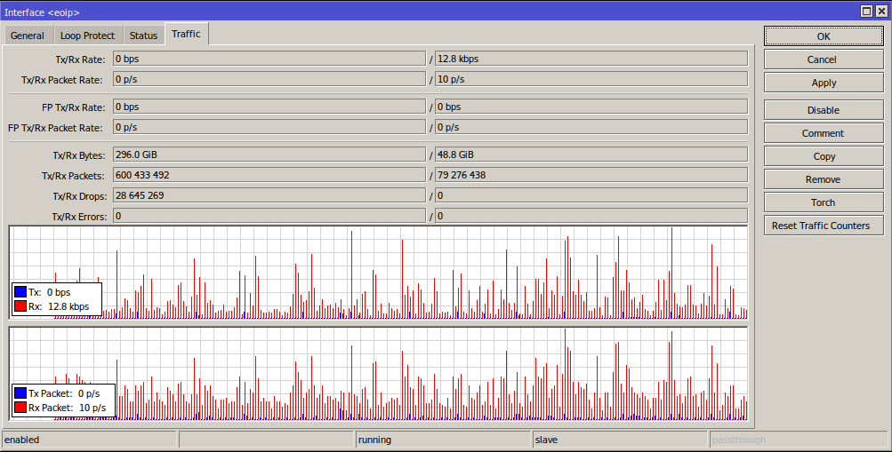
Helpfully for this project, RouterOS also supports Ethernet-over-IP:
Ethernet over IP (EoIP) Tunnelling is a MikroTik RouterOS protocol that creates an Ethernet tunnel between two routers on top of an IP connection. The EoIP tunnel may run over IPIP tunnel, PPTP tunnel or any other connection capable of transporting IP.
When the bridging function of the router is enabled, all Ethernet traffic (all Ethernet protocols) will be bridged just as if there where a physical Ethernet interface and cable between the two routers (with bridging enabled). This protocol makes multiple network schemes possible.
A Cloud Hosted Router or CHR runs in AWS with an Elastic (aka static) IP. A CHR is an x86 Virtual Machine running RouterOS.
An OpenVPN tunnel connects one of the routers at Home to the AWS instance with the Home Router being the client and dialling out to AWS.
Originally I had setup NAT chain rules to forward traffic over the VPN interface but it proved much simpler to use an EoIP tunnel - even though it adds in traffic overheads, for my use case that doesn't matter enough to offset the simplicity.
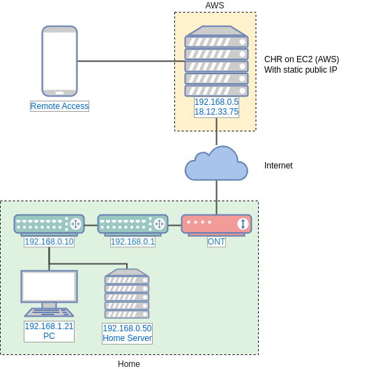
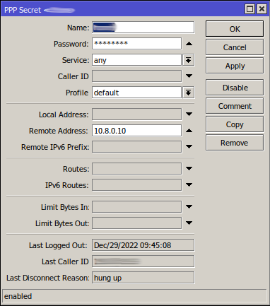
The "Core Switch" at 192.168.0.10 dials the OpenVPN connection out to the CHR 18.12.33.75.
The CHR provides peer IP addresses on the 10.8.0.0/24 network.
The VPN client has a fixed IP on the VPN link, as does the CHR.
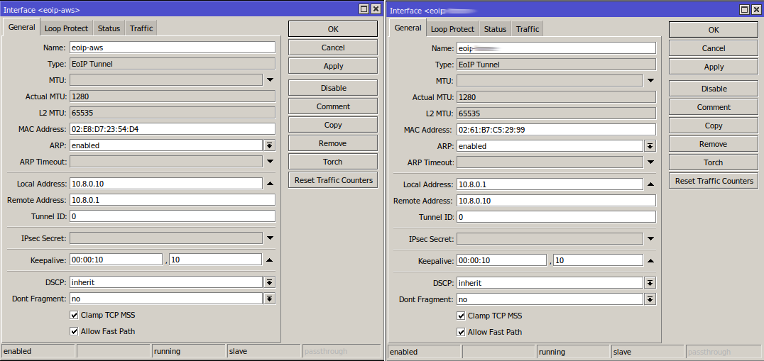
The Core Switch and CHR both have an EoIP interface where the remote IPs point at each other respectively.
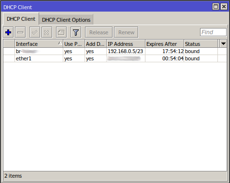
The CHR runs a DHCP client on the EoIP interface (via a bridge) which it gets a fixed lease (a.k.a reservation) IP of 192.168.0.5
The CHR then has dstnat NAT rules to forward traffic on specific ports that comes in on the public interface to the private network of 192.168.0.0/23 which it knows to reach over the EoIP interface.
The Configuration
The following screenshots and comments show the configuration but this is not a step-by-step configuration guide, nor specifically an example of best practice or ideal settings.
CHR in AWS
The official CHR Image can be found under the EC2 launch wizard:
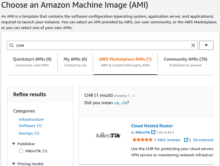
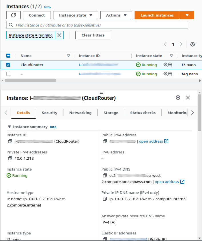
A tiny instance (like a t3.nano) is more than enough for this.
Provision and assign an Elastic IP so that it doesn't change if the instance is stopped for any reason.
Be sure to set sensible firewall (security group) rules at the AWS level since as default the new CHR instance will have winbox (8291) and ssh (22) open to the world.
The default RouterOS credentials can be used to access the instance once booted.
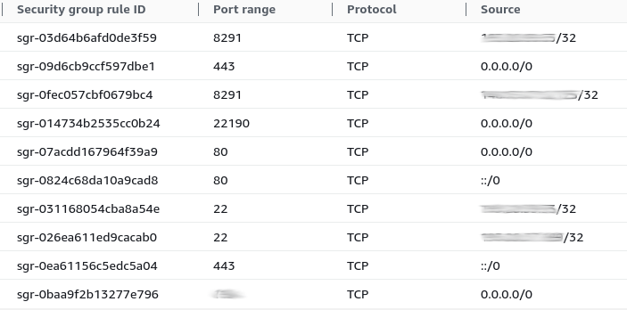
As I am forwarding 80, 443 and 22190 for public access they are open to the world along with the VPN port. All management ports are restricted by IP along with credentials.
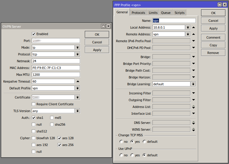
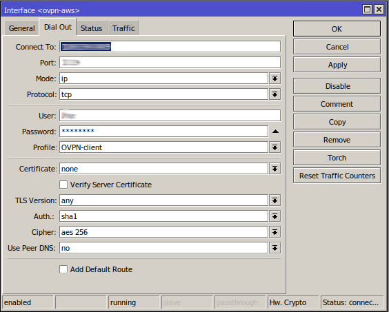
OpenVPN Tunnel
Setting up a VPN tunnel is fairly straightforward with the default settings.
A CA will also need setting up on the CHR.
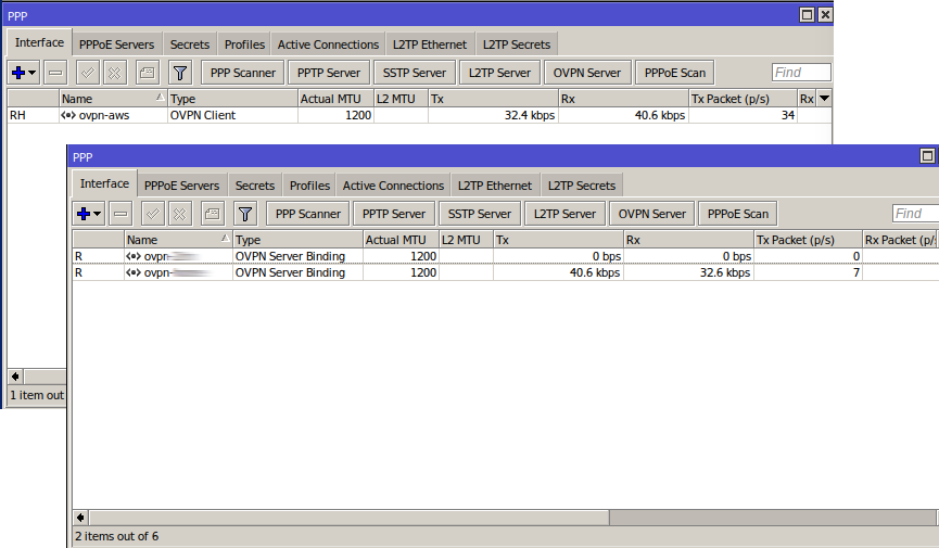
AWS CHR - OpenVPN Server
Core Router - OpenVPN Client
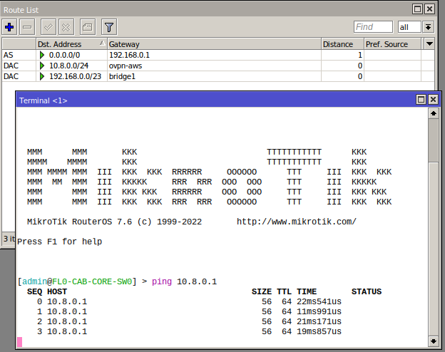
VPN Tunnel Running
The routing tables also show that the 10.8.0.0/24 traffic will route over the respective VPN connections and this can be verified by pinging the other side.
The Ethernet-over-IP Tunnel
Now that the two routers can talk to each other this is particularly straightforward to set up.
EoIP Interfaces
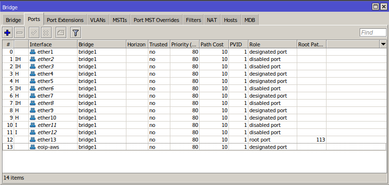
Bridge Rules
On the Home side of the network, the EoIP Interface needs to be part of the rest of the network, and so a port on the main bridge:
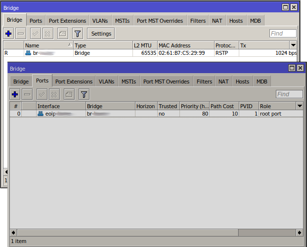
On the CHR/AWS side the interface does not need to be on a bridge but I have added it to one, where the DHCP client can then live:
CHR DHCP Client
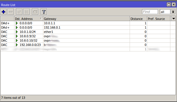
CHR Routes
The DHCP client allows the CHR to pick up the route to 192.168.0.0/23 over the bridge which includes the EoIP interface.
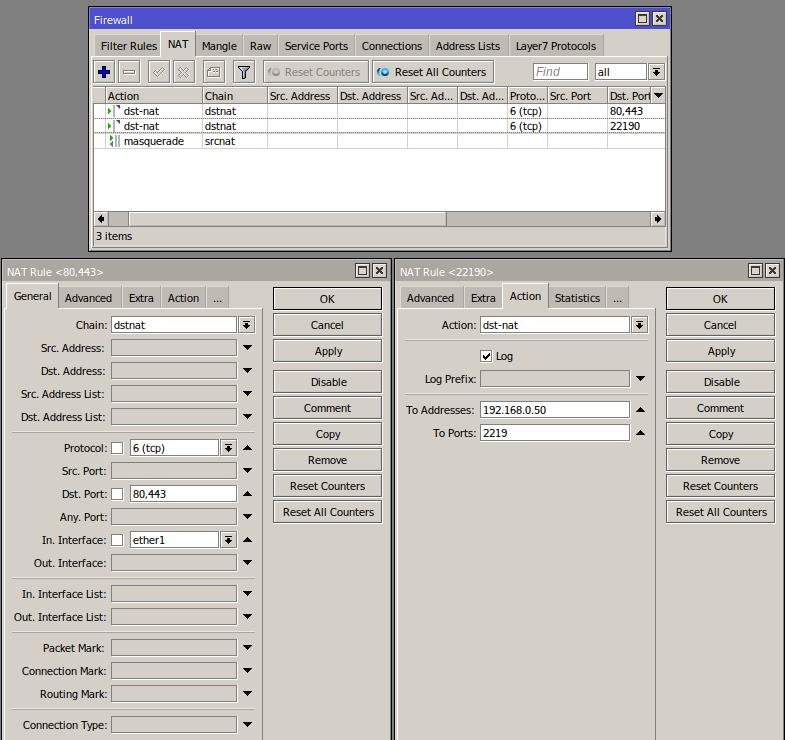
NAT Rules
I am forwarding ports 80 and 443 to my "Home Server" - all services are exposed over HTTPs with client SSL validation.
I also forward 22190 to the Home Server but to an different destination port, hence the extra rule.
The "In. Interface" ether1 is the public AWS interface.
The masquerade rule allows return traffic routing to work with minimal configuration. Other NAT rules can achieve the same thing.
CHR Rules
Conclusion
While more complicated, this setup works well for my needs - it's powerful and flexible but avoids the need to configure a server (e.g. Linux) numerous services to enable routing, VPN, etc (which is what I had setup previously).
By creating a tunnel to an service provider other than my ISP, in this case AWS, I am able to use a public static (Elastic) IP they provide to expose services running at home and provide remote access without needing to know my home IP, worry if it changes or deal with challenges like CG-NAT.
This approach should work with any ISP, so if my home ISP or IP changes I can retain the same public AWS IP for services.
The flexibility of RouterOS means the home network hardware can be inexpensive (£30 or less for a MikroTik hAP lite).
The CHR license has a free tier with speeds limited to 1Mpbs per port - not much, but potentially enough for something like this. License upgrades incur a one time cost, the next level up with a 1 Gbps limit is $45 and they offer 90 day trials.
This setup has proven particularly versatile since we also have a holiday let and I have been able to create a bridge via AWS that lets me access and manage the smart devices there.